A typical system will consist of a Data Acquisition and Control Unit, for each test chamber. The DACU provides continuous monitoring of various TC, RTD, volts, amps, watts, watt-hours, flows and pressures. Each DACU contains front-end measurement devices and/or analog PLC’s, power supplies and I/O terminals. All equipment is housed inside a NEMA 12 enclosure for location near the test chamber.
The system is versatile enough in its configuration to utilize many different types of measurement and control devices. The Front-end hardware is relied upon to supply the system with all of the measurement data collected from the different input transducers and thermocouples located in the test cell.
The PCTS supports a variety of hardware that is used to perform various levels of environment and control of the test rooms and product.
The PCTS can be configured for a wide range of measurement and control hardware. Small to very large channel counts can be easily supported. Channel configurations can be changed on a per-test basis by the use of point configuration files. Each test server can monitor and control one or more products under test. Each test runs independently from other tests running on the same PC. The front-end hardware can also be shared between multiple tests. This is useful for other test areas (i.e. compressor life testing or heat testing).

The system uses multiple PC’s to perform all testing and reporting functions. The PCTS system can be connected to the plant Local Area Network (LAN) to provide remote monitoring, control and report generation from any PC on the network. Optionally a primary file server PC running Microsoft server contains all test results, procedures, reports and master copies of all system files.
All system transducers use software based calibration. Linear interpolation, polynomial fits or cubic spline can be used for correcting variations in the accuracy of the input or output device. After calibration is complete, the new corrections are automatically loaded. The system database maintains a log file with dates and notes for each calibration.
Real time filtering of all measured values is performed by the software. Multiple filtering methods are applied based on the type of input channel. Each filter models the behavior of the type of input (i.e. watts, amps, TC, etc.). This allows removal general system noise before the data is processed. The filter values are set in the system database allowing adjustments for special tests.
Operator security prevents unauthorized use of the system. Each test is owned by the operator. Other operators or engineers can be allowed to view or modify the test. The system maintains a list of all operators and access privileges.
A high level language simplifies test development and modifications. The test procedure describes the method to collect and analyze data from the product under test. The language is based on a Basic format that is easy to learn. The following lists the main functions provided by the language.
Channel point files define the inputs and outputs required by the test. Each test can use one or point files that list each channel and test variables. A title, name and channel reference number are attached to each point. Additionally the point can be enabled for trending or plotting.
Model lookup databases allow a single test procedure to cover a wide range of products. The model describe unique information about each product.
All test stations maintain a list of operator entered data. When a new test is started or a test is restarted, the operator is prompted with previous entries. The entries can also be attached to a product serial number or test ID number.
Microsoft Excel is used to generate reports containing both text and graphics. Template forms are created that position fixed text and values from the test results. Test results are stored in a comma delimited file format. A VB macro sheet is used to load the results into the template sheet. After tests are completed, the result information is copied to the file server under directories based on the type of test.
At the completion of a test, selected result information can be added to a database. Standard software tools (Microsoft Access) can be used to generate reports from the data.
A test can set the chamber conditions, wait for stable conditions and start a test. After test completion the chamber set-point can be changed and a new test started. This allows fully automatic testing of products at various temperatures without operator intervention.
Microsoft Access database files can be attached to tests allowing storage of specific test values. Reports can be created inside Access covering multiple test results on multiple products.
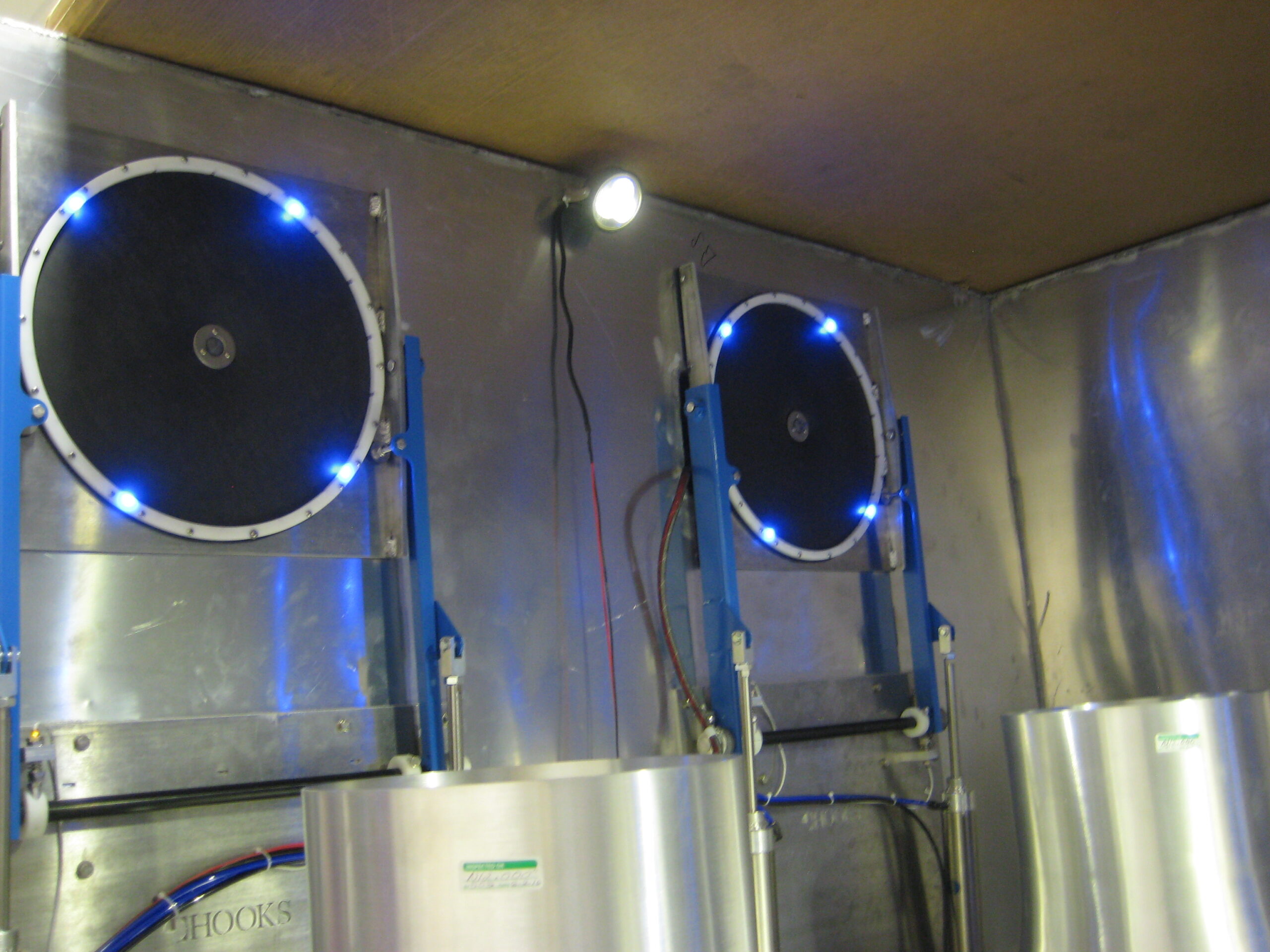
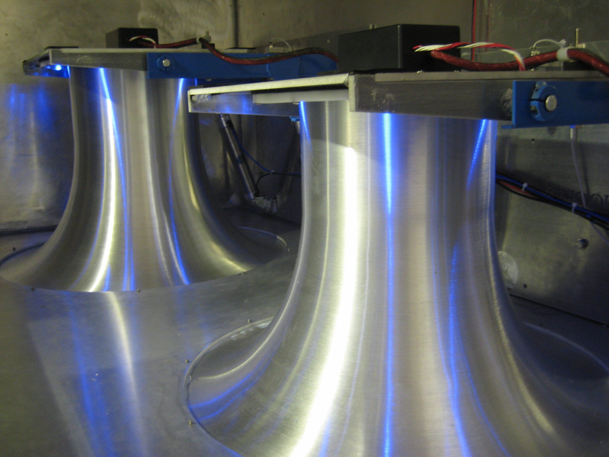
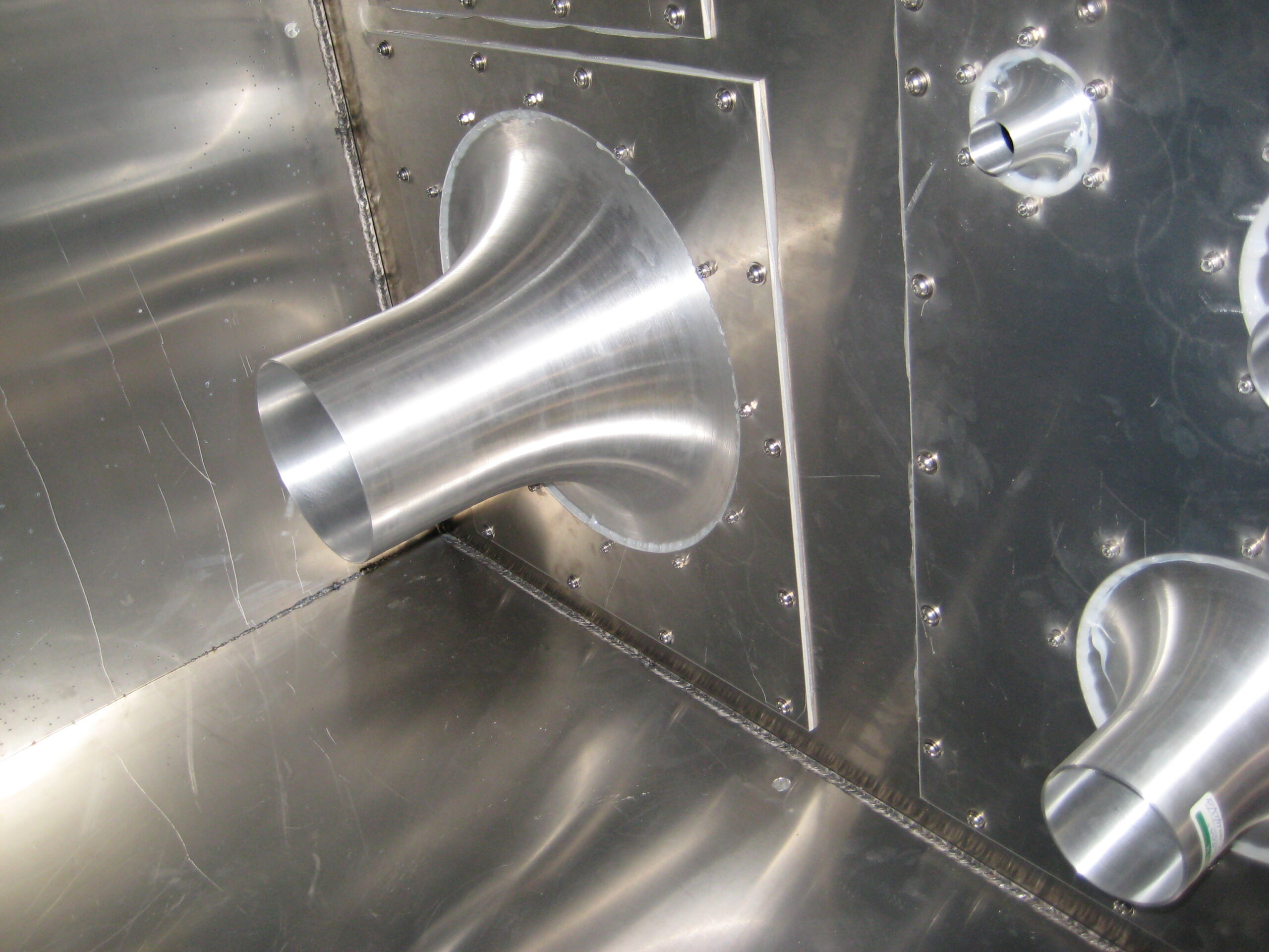
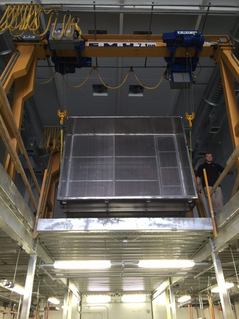
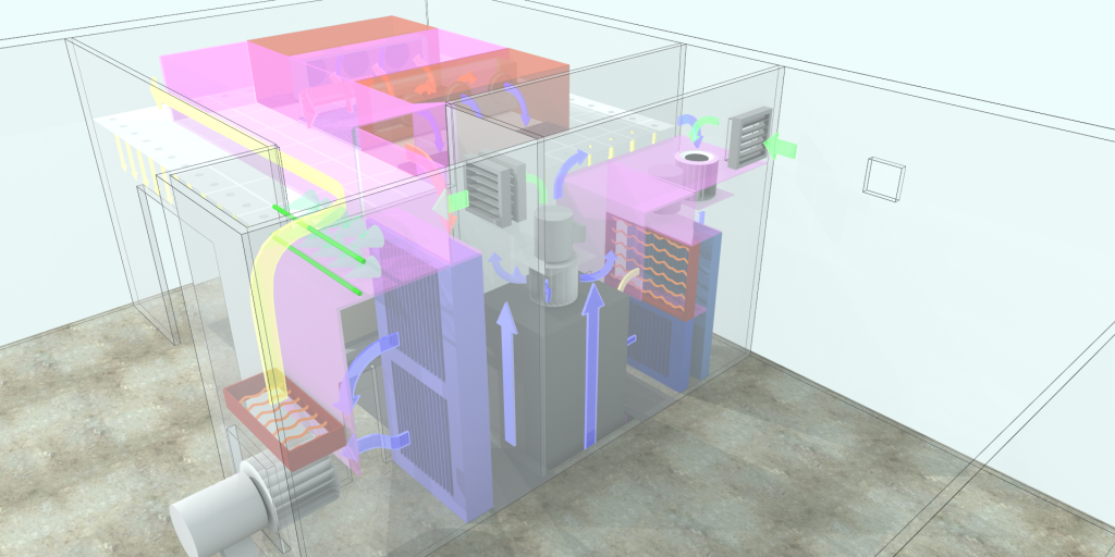
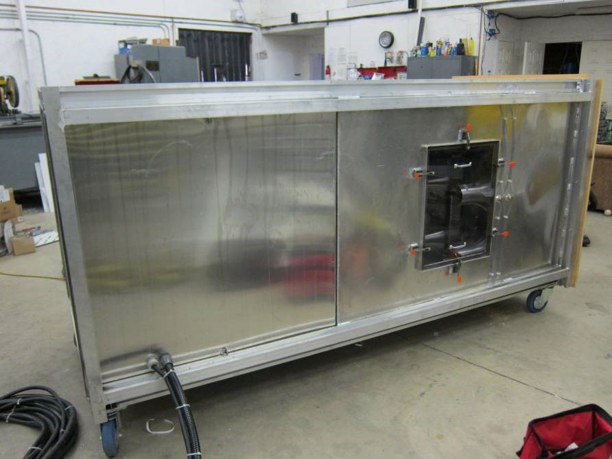
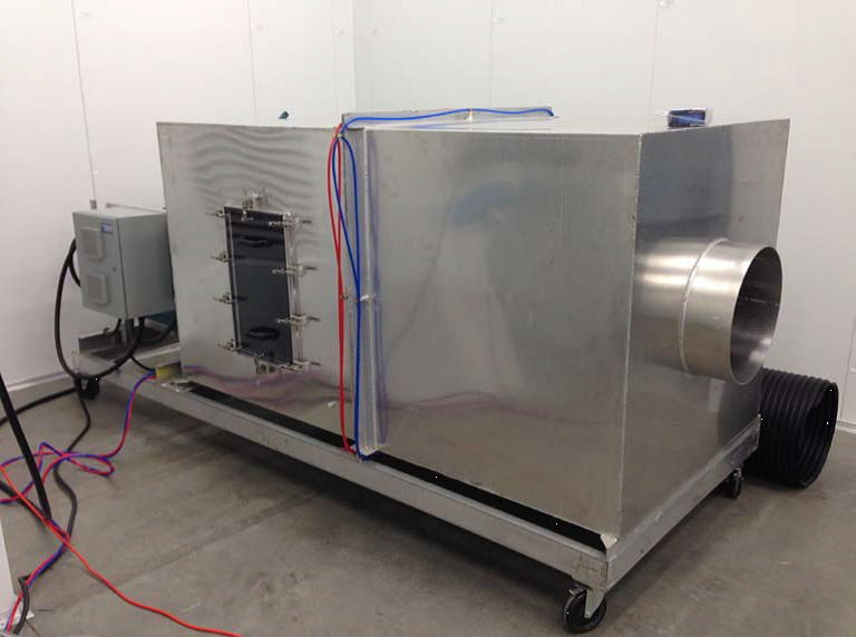
Hooks & Associates builds custom code testers for our Psychrometric Chambers. The code testers can be placed inside or outside the chamber, and we have built a variety of sizes to meet our customer’s testing requirements.
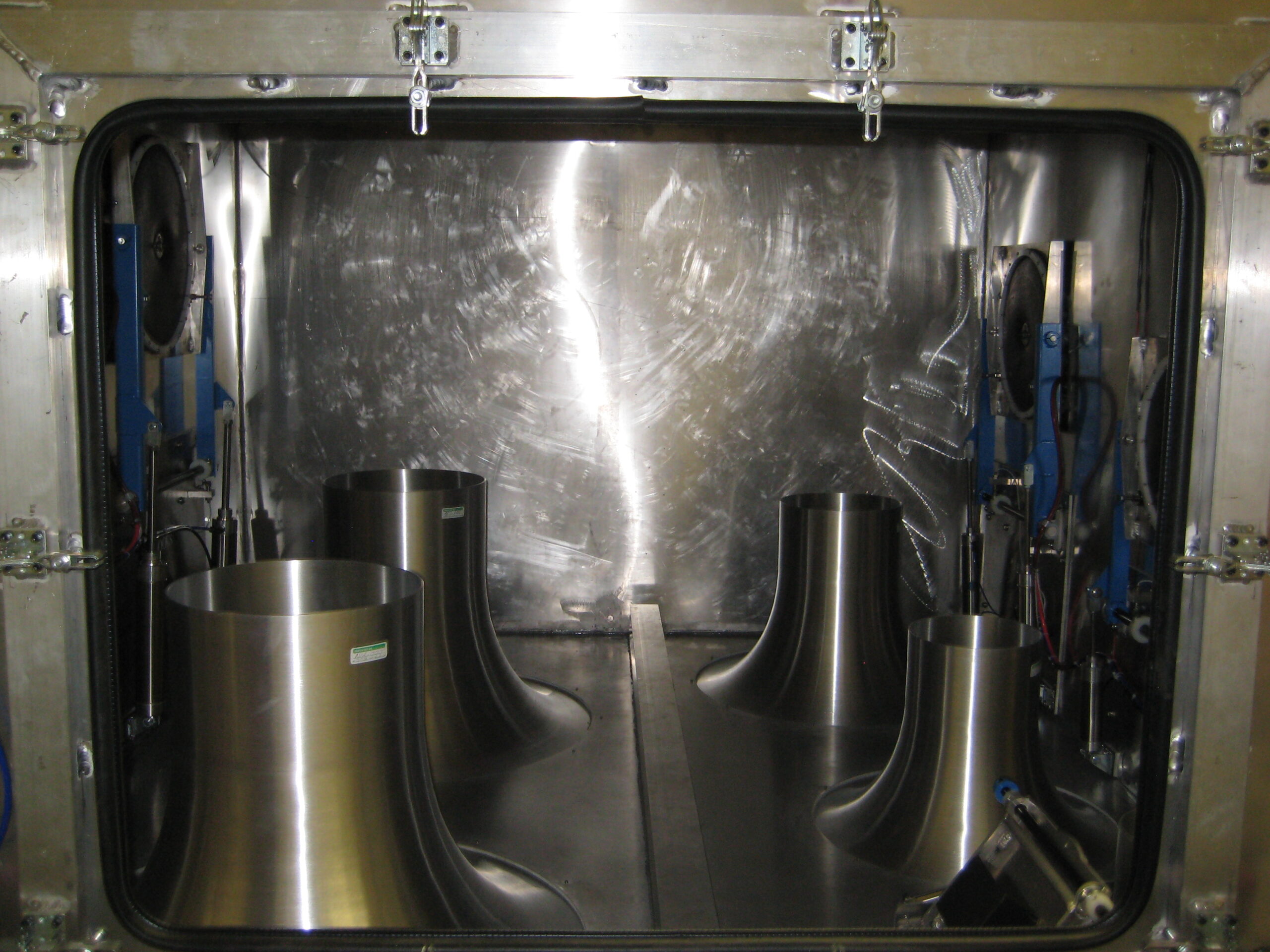
Our Code Tester Nozzles are leading the industry with our infrared leak detection. No other company offers Nozzle leak detection at this degree of precision.